First Public Appearance

In the meantime, I connected everything, except for the flashlights in the side doors. For some reason the LED matrix in the front does not respond – I will address that later. I also added a sound module. Since there are no known sounds for the H015 droid, I added the available BB-8 sound clips – they just sound so good. I will soon post more details here on the sound module.

Last week, I took my H015 to ShreveCon. While nobody recognized him (or her?) – everybody liked him. Here he is posing with a GONK droid.
20171209-ShreveCon-ed2

Mounting the flashlights in the doors

Today, it’s been 354 days since the last entry. So quickly, before this becomes more than a year…

Now that everything on the outside is done, we can work on the “inner values” of the sentry droid. In the first step, we address the side doors which are holding the LED flashlights. We got two cheap flashlights from AliExpress ($0.65 each), which we modify by soldering wires to the battery holders. Then two small holes (for the wires) are drilled into the side of the flashlights. The modified flashlights are then glued into the doors.

The modified flashlights are then glued into the doors. We glue some thin wood to make the four angular pieces that hold the doors, using thin rods.

The angular pieces are glued into the droid – careful, so the doors sit nicely in the openings.

h066

The doors will be opened by two micro servos which are mounted on the base plate.

Bottom details

A very special feature of the H015 droid are its bottom details which are made using LEGO, as documented at rebeldroids.net. This level of detail is, however, far beyond our goal. On the other side, we want at least some similar details – so here is what we did.

h058

We started gluing some cardboard at an angle on the four sides of the chassis. Then we added a second layer with some cut-outs, and glued a few smaller pieces of cardboard on top of that.

h059

Once this is painted black, it shows a little structure, that somehow reminds one of the original.

h060

We also cut a hole for the speaker and glue a few pieces of wood for mounting the electronics and for holding the batteries.

h061.jpg

Chassis and drive system

The original H015 in the movie is using a holonomic drive system with four omni wheels, mounted at 45 degree angles close to the corners. For simplicity (and budget), our version will simply use a drive system with two motorized wheels plus a caster wheel. We are using the same (cheap) motors that worked pretty well with our  astromech droid R3-B9.

h053Since our H015 will be significantly lighter than R3-B9, they should work particularly well.

We cut a piece of 1/8″ plywood to fit exactly below the lower part of the body, plus the pieces which will hold the motors and the caster wheel.

h054.jpg

The plywood pieces are glued and then the motors and caster wheel are mounted.

h055.jpg

h056.jpg

This base plate provides plenty of space for the Arduino and the additional electronics.

h057.jpg


Front and back displays

After the body and head have been painted, we get started with the details. We use the large areas of  the front and back sides to mount two displays. For the front side, we use five 8×8 LED matrices MAX7219. These are wired in series and mounted behind a piece of plexiglas that we sanded to obtain a matte surface.

For the backside we use a 1602 LCD display (2 rows with 16 characters each), together with a I2C interface which is soldered to the back.

This is how the displays look like:

and here is the full view on the droid from the front

h048

and from the back side.

h049

Upper body and head

The upper body of the original H015 droid consists of white plastic only. But we want to have some fun with our H015, so we add something on each side: Displays on the front and back sides, and doors on the left and right sides.

First we add a second layer of cardboard, before we cut the openings.

Then we build the doors and paint everything with a white primer (Gesso).

Now we add the black paint.

h035

Before finishing everything the paint job, it’s time to think about the antennas. Originally, we planned to have some very simple structures, like round pieces of wood. But then the recent details for the sentry droid became public, and the guys at rebeldroids.net came up with some very detailed plans. At this point we decided that we need a little more detail. So we cut the approximate shapes out of 1/8″ plywood.

Now H015’s head looks like this:

h040

Openings in the lower body

In the meantime, much more information on the H015 sentry droid has been released. H015 was shown on stage at the Star Wars Celebration Europe 2016 and seen at 3:35 in this youtube video. Further images are now posted in the H015 forum at rebeldroids.net. These pictures and the video reveal a few additional details which were not visible in the very first circulating images on which this build is based.However, at this point we planned to deviate from the original anyway. In the TFA movie H015 plays only  a very minor role, which does not require a lot of features. The only things H015 can do is to move and to show its blue light in the neck. We really want to add a few additional features which we will discuss in the next posts.

Today’s post is  about the openings in the lower body. The original H015 has a few openings on the left and the right sides. It seems that the early pictures showed the left side of the droid, and this is the pattern that we use on both sides. In addition, we add a smaller opening in the center of the front side. These openings will hold a power switch, a USB connector (for programming the Arduino), three ultrasonic distance sensors HC-SR04 (for avoiding obstacles), a microphone capsule (for responding to sound), and a volume knob on a PAM8403 2x3Watt amp.

h029

These structures are then glued into the body as seen here:

h030

The elements will be mounted later, after painting.


LED rows for the neck

The H015 droid needs to provide access to the electronics. This could be either through a hole in the bottom plate, or through the neck. The former does not sound like a good idea. In particular, once the antennas are in place it will be a pain to turn the droid upside down. The latter requires the head to be removable – this requires some precise work, to ensure that the head sits straight, without being able to wiggle in its slot.

The original H015 in TFA features some lights in its neck. In the movie, the lights in the neck appear to be blue (at 20:58). In another scene (at 1:36:24) they also seem to be red. Although this might be some reflection, we will use red and blue lights. For this purpose, we use sets of three RGB LEDs, for which only the red and blue elements will be connected. The LEDs are mounted behind some matte white transparent plastic (taken from a gallon bottle of vinegar), to make the lights from the individual LEDs blend into each other. From the appearances in the movie one cannot tell on which sides the LED rows are. We put them on the front, and on the left and right sides.

We start the neck structure with two layers of cardboard to which the plastic pieces are glued. Five more layers of cardboard are added to provide support for the head.

The structures for the LEDs are made from pieces of cardboard, glued to popsicle sticks. These are painted black, and glued to the inside of the neck. Now we cut out the opening at the top of the body which provides access to the inside of the droid.

Four corner pieces (made of three layers of cardboard are then glued to the head. This step requires high precision – otherwise the head may not sit straight, it may have space to wiggle, or it may not fit at all.

After removing the cardboard at the bottom of the droid, the final shape becomes visible.

h028

Yeah!

Head and body

We start from the top. Let’s get our notes, a pencil, rulers, a knife, cardboard, and a piece of wood for cutting.

h001

H015’s head is made of two pieces which will both be glued to a ring. First, the upper head piece is glued to the ring, and temporarily fixed by some metal clips. We cut a hole in the bottom piece and glue it in the same way onto the ring.

This is the head.

Now we cut out the upper and the lower pieces of the body.

These pieces need a little larger separation, so we glue two rings on top of each other.

Then we glue the upper body piece to the rings …

and add some pieces of cardboard as support for the corners.

For the bottom piece we glue the support in the corners first, …

cut a hole in the baseplate, and glue the bottom piece to the rings.
Afterwards we cut out the lower pieces, so that the legs become visible.

At this point, the beautiful shape of the H015 droid becomes already visible. I love that – that’s why I wanted to build it in the first place!

Goals and Plans

Before starting the build, it’s time for some general thoughts:

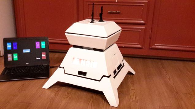
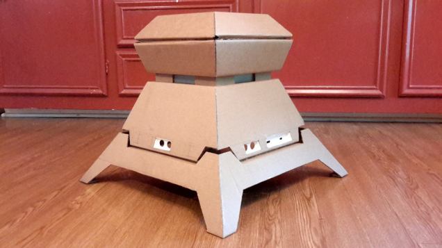
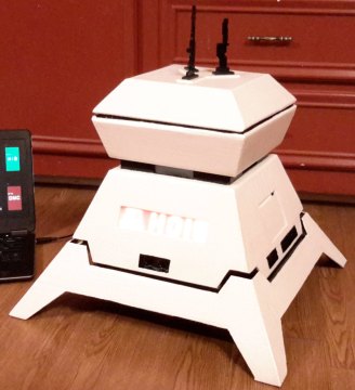
I really, really love the appearance and the shape of the H015 droid.
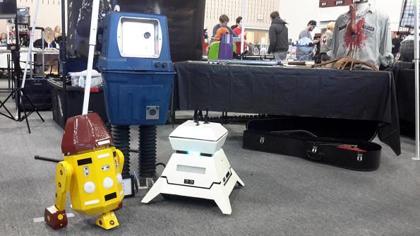
However, the original size (the baseplate is 70cm x 70cm) is a little too large for my purposes. I want this droid to go together well with my astromech droid R3-B9 (built at approx. half of R2-D2’s size) and my mousedroid MSE-6c (built at 90% of the size of the original). So, I decided to build this one at 70%, making the baseplate 49cm x 49cm, and the height 41cm.

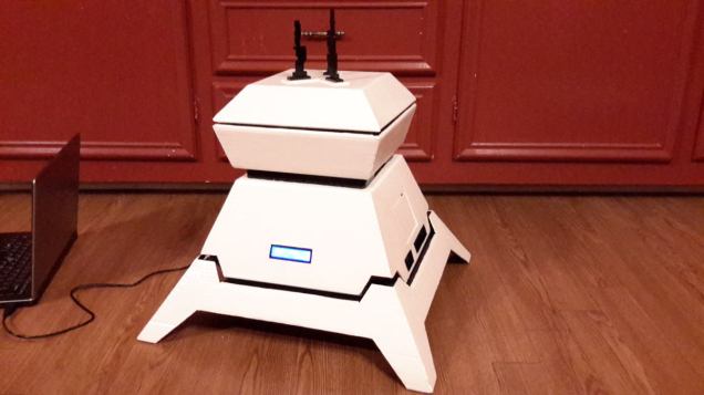
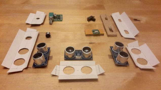
Like the original mousedroid (which moves and makes sounds, but has no other effects), the H015 droid is also rather limited in its functions. In the movie it moves and it can have a blue or red light on the front side. For my robots, I want them to be a little more fun than that, so I aim for a few additional functions. My MSE-6c got an ultrasonic distance sensor (which helps him to brake in front of obstacles), and 4x 7-segment display (which displays the distance to the closest object), and a blue and red LED row on the front side.

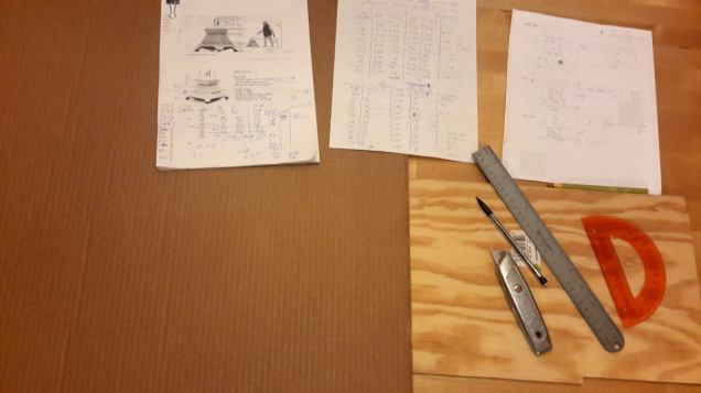
I am planning to add similar features to the H015 droid. So, this won’t be an exact replica, neither in size, nor in the details. And like my other droids, I am also planning to build this one from cardboard. With this in mind, I have created the following plans. These plans are not exactly up to scale. So, one can not simply enlarge these, but has to redraw everything on the cardboard. A great source of free large sheets of robust corrugated cardboard is Sam’s Club (they use this to separate layers of kitchen towels or toilet paper).

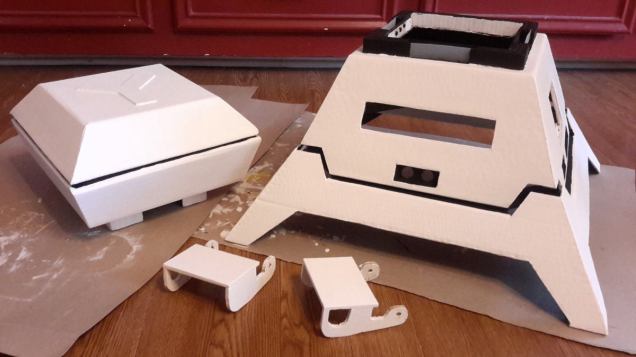
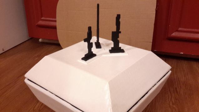
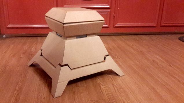
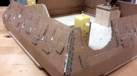
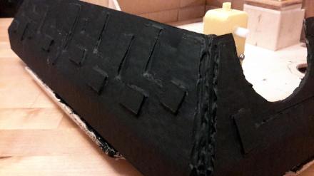
The head and the rest of the body are each made out of two pieces. These two pieces are both glued to a connecting ring which is made out of one layer of cardboard for the headpieces, and two layers of cardboard for the body pieces.

Here are the plans for the two head pieces, and for the connecting rings,

… and for the upper and lower parts of the body.

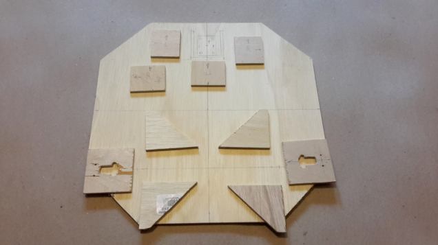
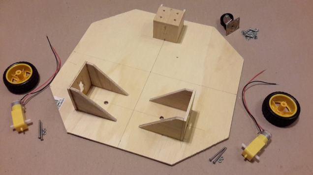
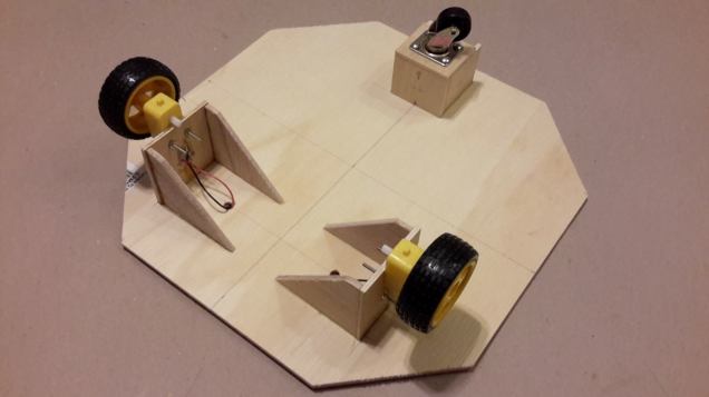
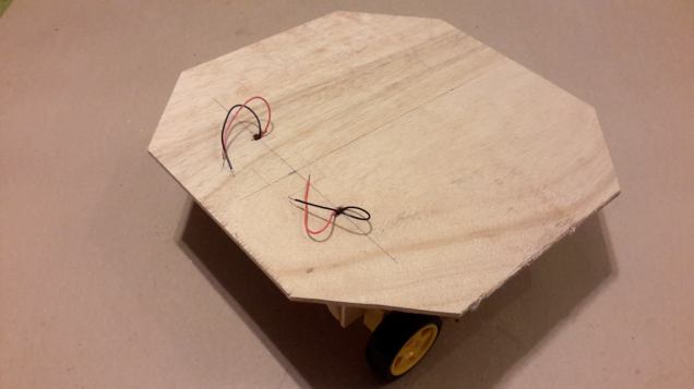
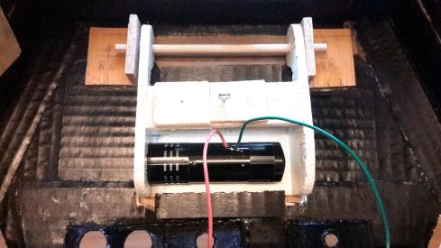
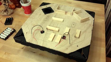
Later, I will insert a piece of wood inside the body, to mount the motors and caster wheel(s).
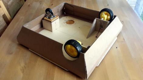
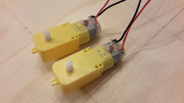